Tampilkan postingan dengan label model. Tampilkan semua postingan

Minggu, 24 Juli 2016

Sailing Model AMYA Star45 Class Construction Deck s Hatches

from John Fisher:
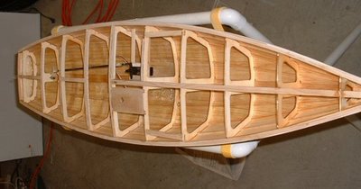
Attaching deck to hull
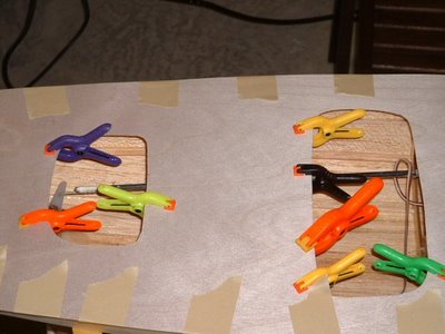
John Fisher photographer


Hull with deck mounted:
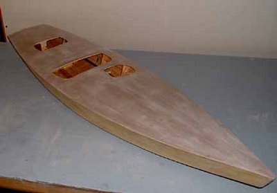
John Fisher photographer


--------------------

HATCHES:

From Phil Geren:
The simplest hatch cover solution I have found for Star 45 is to cut a piece out of Presentation Cover vinyl, which cut-out is shaped like the hatch opening but 1/4 or 3/8 of an inch larger on all sides. Then, apply electricians tape (1/2 or 3/4" wide) all around the perifery, so that half the tape is on the vinyl and half is hanging over the edge.

Presentation Cover vinyl which I get at Office Depot is about 15 cents a sheet; it is about 0.008" thick; it is slightly over 8.5X11" in size; a full sheet weighs about 16 grams; it is stiff, but flexible; it is crystal clear, but if you want it opaque, just wet sand it with #400 grit wet or dry sandpaper.

Position the hatch cover over the hatch so that the tape extends evenly past the hatch opening an equal distance all around, and then just press on the tape to stick it to the deck. Its waterproof, durable.

You can make spares and stick them to another piece of vinyl and carry that with you to the races. That keeps spares nice and flat and keeps the tapes sticky side clean for future use. A set of these hatch covers usually lasts me all season. At lunch, I take one cover off to allow the boat to dry out, sticking the cover to a dry vinyl sheet to keep the tapes sticky side clean.

Photo is Star 45 #778, freshly rebuilt for the Nationals this year, and a set of covers on the floor next to her.
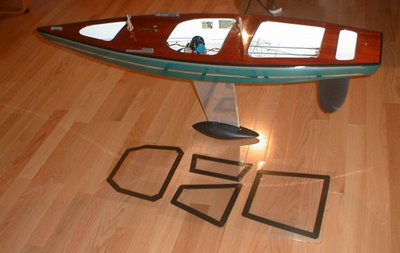


Phil Geren photographer


--
from Uncle Dave:
I pulled one of my old Star45s from the attic and have it here in my workshop. It has a fiberglass Sirius 45 hull, a aircraft ply deck and aluminum keel fin. Unfortunately it is not one of my finest examples of workmanship or painting. However Ill suffer the embarrassment and use if to show some one style of hatch construction.

Carrying around a model around out of the water is no big deal. Taking a model out of the water can be something else. You first need to hang onto the model. Then find a place to take hold to lift the model. This is one of the reasons I have used easily removable hatches. You can grab the model through the hatch, fingers under the deck and pick it up. Of course a thin ply deck the model deck and hatch construction needs to be strong enough to withstand pulling on the deck and lifting a twelve pound plus model. Therefore I braced my decks around hatch areas.

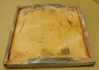
First I built a flanged frame for the hatch to sit in that also extended under the deck and attached to the deck bracing.
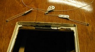
dlm_hatch_a.jpg

Then I built a hatch cover based on the size of the hatch. Initially the hatch cover was made to fit very loosely in the hatch. I then took some silicone (tub seal or similar) squeezed a bead around the shelf/lip of the hatch. The covering the hatch opening with food wrap poly sheeting Id push the hatch cover in place down into the silicone. This made a nice water tight gasket around the edge of the hatch. After waiting a day Id remove the plastic, trim and silicone that showed topside. With the silicone dry, pop the hatch cover in place and check the fit.
dlm_hatch_b.jpg

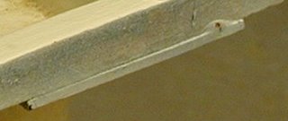
I placed a strip of magnetic tape on either end of the cover and on each end of the hatch frame.
dlm_hatch_c.jpg

When the hatch cover and hatch mag tapes touched they pulled together. This magnetic tape is neat stuff you can pop the cover in place and it will stay put.

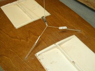
Typically I made my hatches about 4"X5" giving me plenty of deck to the sheer.
fixed_travelersml.jpg

I heavy weather if the model might go over on beams end Id cover the seams with tape just to be extra watertight. A 4X5 hatch gives room to get inside, adjust winch, radio etc, and to remove any water that got into the bilge while sailing.

Read More..

Rabu, 13 Juli 2016

Sailing Model AMYA Star45 Class keel mount using keel trunk

Here is how John Fisher built two Star45 keel trunks. First he make a aluminum mandrel that is the same size and shape of the top of his keels. Next he waxed the aluminum and then put a single layer of wax paper over the mandrel.

He used a light spray of 3M 77 to stick the ends together on the second one. The first one had a pc of tape, which is now a part of the trunk.

The mandrel with waxed paper is wrapped with glass which he again used 3M 77 to hold in place. He has not verified that this doesnt have any long term effects to the glass so use at your own risk. John used 2 layers 3.2 oz glass with glass tape on the top and bottom edges to help add some stregth. Usually he would add kevlar, but that is not allowed in the stars. One the glass was in place John wet the whole thing with resin. If you dont have any way to vac bag the trunk, just let it cure and remove the mandrel. The trunk weighted in at 1 oz.

John has a food vacuum sealer so he put a release paper over the top (wax paper with holes in it), then breather cloth (he hasused paper towels in the past), and then into a food saver bag for the night.

To remove the mandrel he used a hammer and a vice. He knows that sounds severe, but that is what it took to get the mandrel back out. He started by placing the mandrel into a vice with smooth jaws. The jaws were just far enough apart that the aluminum would fit between them, but not the fiber glass wrap. Then he tapped the mandrel out. He points out how much force it took for him to get this apart so you can design your keel top with this in mind.

Photo 01- mandrel before prep
Photo 03 -mandrel with glass, ready for resin
Photo 04-keel trunk in food saver bag. You can see the resin going into the breather cloth.
Photo 05 - keel trunk off the mandrel, note the tape. 2nd trunk used3M 77 instead.
Photo 06 - Trunk on the keel.


The following picture shows the way that John aligned the keel on his second boat.
Since the keel is plate and 1/8" thick I laid a straight edge on it and
aligned it with the pc at the center of the transom. I did this on both
sides to make sure it is centered as well.

To capture the top of the keel box he added 2 1/8" X 3/8" spruce blocks
to the top of the keel trunk and glued them to the king plank. The photo also shows the glass tape He used to reinforce the
radio tray.


John Fisher photographer


===

here is an alternative keel trunk (from Uncle Dave)

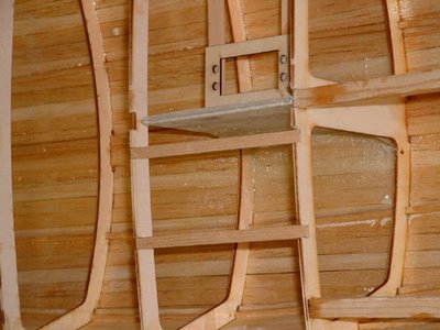
I poked my camera down into the Sirius 45 and snapped a couple of pictures showing how the keel is attached to allow it to be removed and another installed.

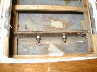
The keel is a aluminum fin with my flat bottomed bulb. The keel trunk is assembled over the keel fin before mounting the trunk in the hull. The trunk is pretty simple. Two pieces of 1/8 ply on either side of the fin. Cut flush across the top of the fin. Height is determined by the amount of the fin to extend into the hull. Length is determined by the shadows or braces to support the fin. A filler pieced goes between the sides so that fin can be slid own and out of the trunk.

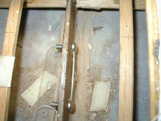
Before gluing the trunk up it is very important to coat the insides of the trunk to make the sides of the trunk as water resistant as you can. The the fun part is placing two mounting bolts through the sides of the trunk and thought the keel fin. I think the two bolts in the picture were 1/2 long 3/8 inch dia.

DLM_s45_trunk_a.jpg

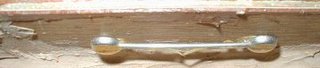
I placed a heavy wire through the both the bolt heads so I could turn the nuts on the other side.

DLM_s45_trunk_b.jpg

With the nuts removed the two bolts simply push to one side and the keel fin mounted or removed as the case may be. In my models the height of the fin inside the model is low enough for a swing arm sail control to fit properly. I use Probar (now Dumas) SCUs.

Before building the deck I simply dropped the trunk (with keel fin) through the slot in the bottom of the hull so the trunk rests on the keelson. The hull being fiberglass the trunk if filleted with the bottom using some auto body resin-paste. I think I also used the resin paste to mount the keel trunk in my wooden models (memory escapes me its been years). The ends of the trunk are braced to the chine to with stand leverage forces from the heavy keel bulb and sailing stresses.

DLM_s45_trunk_d.jpg

When the two bolts are tightened they not only hold the keel in place they also pull the sides of the of the trunk tightly together. With the tight fit one should expect the keel fin may stick in the trunk if some sort of lubricant (silicone) isnt used.

Read More..

Rabu, 29 Juni 2016

Steps toward building a sailing model


Building Displaying Sailing
Model Boats and Ships

So you want to build a sailing model
Find plans for a sailing model, buy or find on-line.

Join a model boat forum for advice.

Buy or borrow books on boat building.

Decide on type of planking and wood to be used to build the model.

Set aside a work space for building.

Review the bill of materials need to build the model and buy the materials.

Order deck and mast fittings.

Order mast (if you are buying the mast) and order sails (or sail material).

Choose the radio system, buy a sail control unit, Order keel bulb or get advice and discuss issues of building your own.

While the hull is under construction build:

Keel fin and ballast bulb

Rudder assembly

Make or assemble spars ( mast and booms)

Build cradle to hold boat under construction and when finished.

Test Radio System and sail control unit

After hull is planked:

Install keel trunk or make provisions for mounting keel.

Install radio and sail control unit, Then remove while construction continues.

Construct deck and hatches

Install/mount deck fittings

Test access to radio and sail control inside the hull.

Provide a exit guide for radio antenna so it can be attached to mast or stays.

Install power switch for turning off batteries

Test mount keel

Paint hull, rudder and keel

Assemble hull, rudder and keel

Set up mast and boom.

Install radio controls.

Check running rigging.

Attach Sails

dry sail model

--

Sail
Display
Storage
Read More..

Build a Model Sailboat !!

The information used for the " Model Sail Boat Building, Making A Wooden Star45 R/C Sailing Model" includes posts found on the companion blog: The Star 45 R/C Model Sail Boat - Builders Journal


"Model Sail Boat Building, Making A Wooden Star45 R/C Sailing Model" is a start to finish, step by step, building manual. Including directions for covering a wooden star with fiberglass.

With the popularity of radio-controlled models, the number of people interested in owning a model yacht has also grown - in geometric range. As with model aircraft, the choice of sailing models runs the gamut from childs toy to sophisticated craft.

Over the past 30 years I have fielded many questions regarding the choices and considerations which go into selecting a radio-controlled sailboat.

Four questions are asked over and over by prospective skippers: How do the radio-controls work? How much do they cost? What do I look for when I buy mine? And, where can I get plans and instructions for building a sailing model?

The modern R/C model sailing craft is as different from a toy boat as a museum display model is from a childs tinker-toy creation. A model sailing craft operates with the same sophistication of design as any full-sized yacht

The AMYA STAR 45 Class discussion group is a terrific place to exchange ideas and talk about building Star 45 models for racing in AMYA regattas.

Feel free to contact me, Dave Mainwaring mainwaring @ rcn.com
Read More..

Minggu, 26 Juni 2016

Sailing Model AMYA Star45 Class building rudder

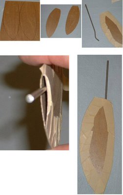
Here are some photos showing one way to build a rudder quickly and easily. The quick overview is cut out the shape in a thin material, tape the sides together, insert the rudder shaft, fill the inside of the rudder with epoxy. This takes about 10 min or so to do. Followed by installation in your boat.

John Fisher

Lay out the rudder shape on a sheet of 1/64 ply. On other class boats John used a single layer of a 6 oz carbon fiber layup, so you could also lay up some fiberglass for use on the star. To do a glass layup, just take a sheet of 6 oz or heavier fiberglass, a sheet of lexan or plexiglass, and some resin. The first step is to spread resin on the plexiglass, then apply the fiberglass and then make sure it is all wetted out. Once cure flex the plexiglass and the layup will pop off.

Shows the two sides cut out of plywood, these could be fiberglass instead. Straight sided shapes like shown and the star plans are easier to make.

Tape the two sides together with masking tape. With curved shapes He taped them together then insert the shaft and resin. If you use straight sides on the rudder you can tape one side and then open it up like a book, apply resin, then close and tape shut. The open book method uses less resin but only works with sq or straight sided shapes.

Note the bend John put in the shaft to prevent it from turning inside the rudder.

Shows the top open to pour in resin. John uses a syringe to pour in resin once the shaft is in place. You can add micro balloons to the resin if concerned about weight.


Installing Rudder in Star 45

rudder brace

rudder tube


tiller

rudder link

John Fisher photographer

Read More..

Senin, 06 Juni 2016

Build a Model

The vast majority of my plans customers seem to be first-timers, and the building process - particularly visualisation - can be quite intimidating. Without any shadow of a doubt there are three primary aids in making a good start: -
  • reading the correct text books (be extremely cautious about internet forums);
  • spend plenty of time studying the plans;
  • build a scale model.
The first two are self-explanatory, and I provide a recommended reading list with my plans, and try to make the plans detailed, supported by a comprehensive set of instructions.

Phoenix III plans - 30 sheets of A3 drawings and 50 pages of illustrated instructions.
Making a scale model is relatively simple if you follow the plans of the full-szed boat. The model doesnt have to be a masterpiece, but should follow exactly the sequence of constrution as specified in the plans.

Sometimes I build an exact replica using scale thickness plywood and scale thickness lumber of the same density as the full-sized boat. This allows me to test trim, stability, flotation and other elements of the design. At other times, I model only a section of the boat to examine things such as panel developments and curvature.

Hull panels for my Three Brothers design cut from 1.5mm Hoop Pine marine plywood to produce a 1/8th scale model.
Scale stitch-and-glue process
Hull panel developments being tested.
Anticipated shape confirmed as being developable
Sometimes people find it difficult to locate scale thickness plywood, but using balsa or other timber can still produce a worthwhile model for shape visualisation, and to help one understand the construction process.

Dan Taylors model of Phoenix III
Another photo of Dan Taylors Phoenix III
My good friend Doug Laver is building a model of First Mate just for the fun of it. He intends sailing the boat using radio control, and has replaced the centreboard with a ballasted fin keel to make up for the lack of crew weight out on the gunwale.

Dougs First Mate parts cut at 1/5th scale using plywood
Lots of little clamps in use
Ballast keel inserted in centreboard case from below
First Mate waiting for her lead ballast and her rig
Modelling may appear to be a time-consuming business, but in the long run it usually saves time - and it is fun!
Read More..

Kamis, 02 Juni 2016

The Star45 Model Sail Boat A radio controlled R C Sailing Model


The Star 45 is a 45" long hard chine hull; semi-scale model of the full-size Olympic Star. They weigh 12 pounds plus, have 12 inch beam. They are easy to scratch build and sail. Well suited for building by by the novice builder and by the skipper looking for a classic looking model to race.
Read More..

Rabu, 25 Mei 2016

Mid Atlantic Small Craft Festival and Maritime Model Expo

The Mid-Atlantic Small Craft Festival takes place every year at the Chesapeake Bay Maritime Museum in St Michaels, Maryland. It happens next weekend Saturday 3rd and Sunday 4th October. This is the 33rd running of the very popular event and this year it has been joined by the Maritime Model Expo.

Hundreds of amateur and professional boatbuilders bring their boats to this event, to participate in on-the-water events and to show their boats. This festival has a full program of boatbuilding demonstrations and other educational opportunities, in addition to the many permanent and temporary displays of the Museum. The model displays and exhibitions will take place on and around the model pond. There are also opportunities for scenic boat rides all weekend and a race to watch on Saturday afternoon, as well as live music and plenty of food to keep you going.

The floating fleet of the Chesapeake Bay Maritime Museum. CBMM photo
I will be there for the weekend, with my Paper Jet skiff. When not on the water sailing, my boat will be somewhere on the waterfront and I will be somewhere nearby. If you want to chat about our designs or my books, ask questions about boatbuilding, sailing or ocean-crossings, or just to talk boats, come looking for me, I wont be far away.

I will also be at the Festival Dinner on Saturday evening and will be the speaker for the evening. My subject will be my boat designs, concentrating mostly on those under 20ft long. This will include the open boat circumnavigation of Anthony Steward on one of my 19ft designs.

Anthony Steward leaving Cape Town at the start of his circumnavigation.
If you are looking for something to do next weekend and are within driving distance of St Michaels MD, come to the Chesapeake Bay Maritime Museum for a memorable boating experience. I look forward to meeting you there.

To see our boat designs, small or large, go to http://dixdesign.com or http://dixdesign.com/mobile.

Read More..

Kamis, 19 Mei 2016

A Real Hull Model

The Calendar Iands Yawl

Hull Modeling in the flesh: part 1

CNC cutting parts for a quarter scale model

The 3D computer model is sliced up into sections that become molds for defining the hull shape.


You can see the molds formed now, trimmed to the hull surface,  and one more to go!
The hull is planked and ready to be broken up into the "flat" 2D geometry.

A neat screenshot that shows the 3D and 2D nature of the work: in the foreground is the 3D hull model. In the background is the geometry flattened onto the "construction plane".
This is the file with the 2D geometry as received by the CNC cutter, CNC Routing & Design in Camden, Maine. Tim will load the file into his Shopbot software, make toolpaths, and cut the parts.

The ShopBot machine cuts to my lines with a couple thousands of an inch accuracy. These are the planks of the boat, the bottom keel plank in the center and the sheer strake to the far right and left.

The molds of my quarter scale kit around which the planks will be wrapped and checked for fairness and for fit.
Read More..

Jumat, 13 Mei 2016

Sailing Model AMYA Star45 Class Planking bottom of hull

From John Fisher:

Photograph by John Fisher


Photograph by John Fisher


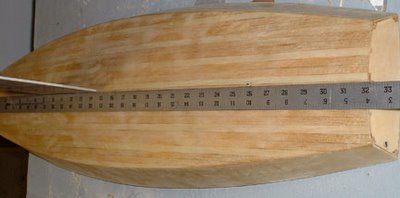
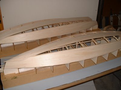
Since it was requested here are a couple of photos of planking the
bottom of my two wood/glass stars. photo 01 is the bottom of the first
star about half way done. Planks are 1/16 X 3/8 balsa. These were cut
from a 48" long sheet. Weigh your balsa before buying it. I would not
use a 3 X 48 sheet that weighed in at more than 22g. It takes 3 sheets
to cover the bottom and you could add another 1 to 1.5 oz by using
heavy balsa.

I started in the middle and worked to the outside. I sprayed the
shadows with kicker, then put down a plank, then added super fast CA to
hold it down. If the kicker was not dry enough it would cure before it
wicked into the joint which would cause the next plank to not fit
correctly. I had some variation in the planks, but once they were
glassed the bottom smoothed out quite a bit.

If I were to do another one I would add the half frames. I will be
adding them to the DXF files in the next couple of days for anyone
wishing to cut a set.

Picture shows the bottom after it was completely planked. On the
second boat I got a nice pattern on the bottom since the balsa sheets
had different grain structure. I sanded the sided flush and got the
bottom relatively smooth, but not perfect. With the balsa planks they
were flexible and if sanded too much you get thin spots at the frames.
The glass smoothed out inperfections. If doing a hard wood bottom the
planks should fit better than what I did with the balsa.

John Fisher 2006 August 15

Read More..

Senin, 11 April 2016

Sailing Model AMYA Star45 Class Decking

From Terry Forbes:
"The Star 45 boats that I have built have decks made from bass wood strips that are 1/4" X 1/16". I find them easy to use and easy to bend with out fracturing. I use thick ca to bond to hull frames and to the adjoining strip. When is have it all glued down, I sand with 120 grit and then 200. I use a soft rag to wipe off deck but leave the cracks filled with the sanding dust or "wood Flower" I then give it a thinned coat of slow cure epoxy. This first coat will soak into the wood completely. I then use un-thinned epoxy for the second and third coat, wet sanding and tack ragging between coats. If you want a really glassy deck, I use a finish coat of Captians Spar varnish. I have used this finish technique on full scale boats and all of my Kayaks. Very nice and durable finish. The decks go on easy and I try to stagger the strips one dark one light. I built a full scale star in the early 60s and had a striped planked deck. I like the look and it builds light. It keeps the hull true as sometimes when you add the deck using plywood it can cause it to move around. I will post some photos of my next hull as it comes to life. I have constructed a ships-way. I used the formers that are shown on the IMYA star plans. I now only have to cut the actual hull formers. I Stack cut 4 at a time on my trusty Dremmel Moto Shop Saw. I have added some lighting holes here and there. All in all I can have a hull lofted in 1 hr. and the sides on that evening using 20-min epoxy to coat the frames and the inside of the hull side. I first made my side peaces out of poster board. This allowed me to get the fit close and have a template to trace the sides for cutting. "

Read More..

Kamis, 07 April 2016

Covering Star45 model hull with fiberglass and epoxy resin

From: "John Fisher" racer577 at citystar.com
I have used the 3.2 oz satin weave on 7 boats now. The first was a single layer and now that hull is 4 or 5 years olds it is showing wear and tear. I went to using 2 layers to help with durability and to have more material for sanding. Another thing I like about the cloth is that is drapes very nicely and easily will cover the hull with one pc. On my 10Rs I have used 2 yards folded in half to do the hull. On the star I was concerned that it would be too wide for a single yard. I ended up with more than enough material so I cut it on the diagonal.

The glassing starts by laying the glass over the hull. Then I smooth it out so there are no wrinkles. This may take a couple of min. Then I repeat with the next layer. Once the glass is smooth, time for epoxy. I used the 209/105 west systems combination. I used about 10 pumps of material.

I start applying resin to the middle of the bottom with a cheap paint brush. Then I work my way out to the edges of the bottom. Next I do the sides. You need to use lots of resin and dont pull too much or you will pucker the cloth. Once everything is wetted out I go back with a squigee and remove the excess resin. Dont get to carried away or the cloth will go dry again. If in doubt of how this should look practice on a spare block of wood first to get a feel for how the cloth looks as you take out resin.

I did the glassing at about 8 pm and with the 105/209 the resin is still green at 7 am the next morning. When green the glass can be trimmed with a #11 blade in a hobby knife. Then wait another day or two until sanding for full cure. I dont like to do much sanding, instead I try and do most of my fairing by using a thick primer and sanding most of it off between coats. For a clear boat I use polyurethane for a top coat.
Read More..

Sabtu, 02 April 2016

Daves musings about setting up and adjusting sails on R C model Boat

Dry sailing -set up.

Place the model in a stand. Head the model into them wind.

Things that can be moved, and adjusted: Mast step. Mast rake. Boom vangs. Shrouds. stays. Jumper stays. Head stay/jib stay. Sail shape - loose foot. out-hauls.

Attach the sails to the mast.

Set the sail winches in fully trimmed position while allowing sheets to be slack.

Stand the mast with standing rigging attached in the center step position.

Hook the jib swivel into the middle slot of the jib rack. {The jib boom needs to clear the mast.}

Connect the side stays to the chain plates and adjust so the mast is straight and vertical.

Connect the back stay to the back stay fitting.
The jib stay and back stay will need adjusting to set the mast in vertical position.

Move the out-haul of the sails along the boom to give the sails to have some "belly". Pulling the sails out along the boom flattens their shape. The belly (or shape) of the sails will be determined later and the sail shape will be determined by how windy it is.

Where you attach the sheets to the booms will take into account the type and adjustments available for the sail control. The booms should be full out (90 degrees to the center line of the hull) when the SCU is full out and then the booms should be just about over the center line when fully trimmed in. ( I see 10 degrees as suggested angle to center line). The length of jib sheet trimmed and the length of main sheet trimmed is a factor in setting up the sail control so the sails are coordinated properly when sailing. The SCU handles a much longer main sheet than the jib sheet. The use of jib traveler and mainsheet traveler can help position the sails when fully trimmed in. Unless two servos (SCUs) are used a single SCU has the task of coordinating the positioning of the jib and main.

Turn on the R/C and run the SCU.
Test out SCU setting with the sails full out and fully trimmed.

With the mast set up and sails adjusted roughly in position it time to launch and sail.
--
Setting Sail on the water.

Before launching TURN on the radio on the boat. I have seen many models set loose to sail with the on board receiver and sail controls not tuned on and very unhappy skippers watching as their model sails away towards the horizon.

The initial rigging and sail settings are based in getting the model to sail a strait line while close hauled (sails trimmed in) and sailing up-wind.

Properly trimmed the rig will allow the model to sail it self in a straight line with just a minor tendency to "round-up" (i.e. sail itself dead into the wind). If or example you find you are constantly pulling the tiller (i.e. rudder) hard over to pull the model back on course to keep from heading in to the wind your model has weather helm which means your mast and jib must be re-positioned. When tacking if your model stalls into the wind and wont tack? Try different rig setting.
--
Setting Sails
The art of tuning the rig on a sail boat is detailed in books written for racing yachts and boats.

"DINGHY SAILS"
by Jeremy. Howard-Williams

"The Best of Sail Trim:
A Selection of Articles from Sail Magazine"

"Sail Trim: Theory And Practice"
by Peter Hahne

My observations and commentary on tuning are from an amateur and are at best suggestions not professional advice.

Observation Number One!!
Model sails that are single panel loose footed sails rely on the shape of the sail established by the gap between the boom and the foot of the sail. Model sails with "shape" sewn into the sail fabric still are loose footed. Also the lift of the boom also factors in determining the shape and performance of the sails.

Hauling a sail into the center line and at the same time pulling down on the sail can flatten the fabric and kill the sail shape. I like to use travelers to position the sail to the desired point near the center line. Then you can set the point of maximum driving force and not wreck the sail shape.

On a big boat the skipper can changer the suit of sails to match the cut of the sail with the wind conditions. In the case of a model a skipper can change where the out-haul is along the boom, light air adding belly to increase the drive, heavy air pulling the sail out further changing the sails airfoil.

The jib and mainsail work as a system. A skipper has all manner of combinations that may be set relating the two sails. If the models did not have jib clubs they could overlap the mainsail. So model sailors have to adjust the "slot" between the jib and the main to get the maximum driving combined air foil.

In heavy air you may want to close the slot and ease the main so that the jib slightly back-winds the main to help the model sail flatter (less heeling).

Dont forget on a model it is easy to rake the mast fore and aft to trim the sailing characteristics to match wind conditions.
--
A digital camera can be a terrific diagnostic tool for seeing what is happening on your model. You can look at pictures and spot misadjustments. Bends in mast, wrinkles in sails etc. Does you models mast rake forward down wind? Is the back stay bending the top of the mast. How are the jumper/jenny stays adjusted do they balance the tensions between the jib and the back stay?
--
The late Manny Costa of RI always stressed, change one thing at a time to see what changes. He also stressed sailing a pair of models. One model being tuned and sailing against the second to see if the single adjustment improved performance.

Round-Robin racing in pairs is an excellent way to evaluate how your model performs.
Read More..

Minggu, 13 Maret 2016

Dory model and Jig for Birdsmouth Mast


The Deblois Street Dory model is coming together! The approach is to model it at 1/4-scale and line off the planking on the model. These points will be transferred back to a 1/4-scale lofting of the boat and the lines plan will be redrawn to show the chines. A new table of offsets will be made and a couple in Portland will be building the Dory this Fall. Feel free to see a drawing of the Deblois Street Dory by clicking HERE.

In Goat Island Skiff land, preparations are under way to produce Birdsmouth masts as kits or final products, depending on the customers needs. Well make a Birdsmouth mast for our own Goat, first, and ours may be the first Birdsmouth Mast to be used in a Goat Island Skiff! The plan is to market these to other Goat builders who might not have the time or interest in taking on this project. The picture shows the key to doing this on a semi-production basis, a stave taper jig. A long plane will be used to do the work; the plane sole will follow the hardwood guides and the staves will lie in the "bed" between the guides. The staves will eventually match the guides width and carry the right taper along their length.
Read More..

Kamis, 25 Februari 2016

Lester Gilbert on sail making for model sail boats


Model Boat journal

Lester Gilbert on understanding of sail making for model sail boats
Lester Gilbert wrote:
For anyone interested in sailmaking, Ive just finished editing Larry Robinsons "Making Model Yacht Sails" (part 1 only) booklet and have published it as an "international" edition. Ive done this, not to get rich (cos this isnt going to happen to either me or Larry or anyone else connected with this enterprise!), but because Ive spoken to a lot of sailors who want to make sails but dont know the "right" techniques, and who are being misled by incorrect accounts of how this might be done.


A sail block


(Illustration from Larry Robinsons "Making Model Yacht Sails")

From my understanding of sail making, there are two ideas I want to contradict.

The first idea is that you can make sails by accurately cutting a curve on a panel, and then attaching it (stitching, gluing) to another panel. Well, while you might be able to cut a good curve some of the time, your fingers just dont have laser accuracy in them to stick A to B and youll hardly ever obtain reproducible or reliable results. (It might be possible to butt-join the curved edge to another curved edge with a little more reliability, but this doesnt yield what the Equipment Rules of Sailing define to be a seam. Such a sail couldnt be used in sanctioned IOM competition, though it would be OK in a development class.)

The second idea is that you can drape your panels over a "camber board" and get a nice shape that way. Well, let me be clear about what Im knocking here. I take a "camber board" to be a length of curved surface, where the curve is like the surface of a cylinder. In this case, your panelled sail will have exactly the same shape as a single un-panelled sail and, if you wanted a three-dimensional shape, youve wasted your time (though the result certainly looks the part).

Larrys booklet is the only source I know which carefully explains the use and construction of a sail block. I am sure that this is really the only way (in your garage, please, not in some specialist workshop!) to make professional sails, to obtain reliable and reproducible three-dimensional shaping, and to be able to tweak and change your shaping as you learn about the whole business.

(Warning: Yall should know I have ten thumbs and have never made a sail yet. What I have done carefully is to watch and talk to those who do, both professionally and as home builders, and measure the results. Making Larrys booklet available internationally is my way of telling you what Ive learned.)

Bob Wells will be able to ship this within the USA, and I expect that it will also be available from Don Ginthner at GBMY. For worldwide sales, contact SAILSetc. Bob Wells e-mail is "bob" at "islandinet.com", GBMY is "rcsailing" at "gbmy.com", and SAILSetc can be contacted through "sales" at "sailsetc.com".

Ive attempted an analysis of how blocks work on a new page, Sail blocks analysis, and have a new spreadsheet there to help.
Read More..

Selasa, 23 Februari 2016

Stand for tuning finished model

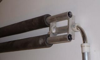
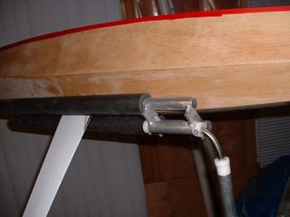
John Fisher sent these in. It might spark some thought for other people as well. He does not claim to have come up with this design, You can use any materials that you have handy, He has a mill and a welder, so his ended up in aluminum. these stands have been built from PVC and Copper pipe as well.

The stand has a vertical tube that is the pivot for direction. This way the boat can feather into the wind. If the ground is soft enough where you sail it can be pushed into the ground. Works fine in so-cal but not very well in colorado. Next there is a H shaped part that holds the boat. His are machined and welded aluminum, but he has seen this part done with copper water pipe or PVC pipe. He added the foam for insulating water pipes to prevent the boat from being scratched. The H should be able to rotate. This allows the boat to heel in the stand when force is applied to the sails. Connect the two and you have your stand. On his stand the connector is a pcs of 1/2" diameter SS tubing bent 90 deg. It provides both motions needed.

tunstand051sml

The boat shown is a hard chine 10R Class called the Diamond.

tunestand71sml.jpg
John Fisher has cutting files available for hard chine model 10R Class as well.
They go fast :-). Johns 10R Class carries 1500 sq in of sail, is 65"
long and only 9" wide.

Read More..

Minggu, 07 Februari 2016

Star 45 Model Sailboat GET THAT TOPPING LIFT RIGHT if you wanna go fast !

By Phil Geren

Of all the go fast stuff I have learned from tuning experts over the past year, the most valuable, and the thing that has provided the most additional boat speed for my 13#-3.5oz Star 45 (the "Fat Lady") is how to get the Jibs topping lift set right. I am doing much better in my racing since learning this.

The curve of the leech of the Jibsail MUST resemble as closely as possible the curve of the leeward surface of the Mainsail when sighting from the foredeck. If the Jibs leech is flatter or fuller your boat will not attain its speed potential while beating and reaching.

The topping lift enables you to get the curves aligned. Tightening the topping lift makes the Jibs leech fuller, more curved. Loosening the topping lift makes the Jibs leech flatter. With a little practice you can get the curves to be identical.

Heres how:

Pull the Mainsail in to the beating position; Swivel the Jib boom with your finger (apply only lateral force, no upward or downward force on the Jib boom) so that when you sight from the foredeck and look up and down the curve of the windward surface of the leech of the Jibsail it is superimposed on the curve of the back (leeward) surface of the Mainsail.

Are the curves identical? If not, is the Jibs leech more curved?
If it is, loosen the topping lift.

If the Jibs leech is flatter, tighten the topping lift.

Make small adjustments. This is very sensitive, and you can get it right if you persevere.
Recheck the need for adjustment after every few heats of racing or if you change anything else.

On sailboats EVERYTHING is related to everything else, and you will need to readjust periodically to maintain your added speed.

Dont have a topping lift? INSTALL ONE NOW! You wont believe the improvement!
Read More..

Senin, 01 Februari 2016

The Star 45 is a one design class of model yachts

PondYachtworks in Scottsdale, AZ.
American Model Yachting Association Star 45 Class

The Star 45 is a one design class of model yachts recognized by the American Model Yacht Association. This boat is 45" long with a minumum weight of 12 pounds. The design is a semiscale model of a International Star. These boats can be scratchbuilt, from a kit or purchased complete.


Read More..

Senin, 08 Juni 2015

Popular Sailing boat model plans

Free Model Boat Plans Free Model Ship Building Plans Model Ship Plans Blueprints Golden Hind Ship Model Plans Free Model Ship Plans Blueprints
Read More..

Sabtu, 06 Juni 2015

Complete Fast electric model boat plans

This Fast electric model boat plans these days i discovered the actual Fast electric model boat plans Detailed information about Fast electric model boat plans it is not easy to obtain this information In the survey I get that not a few people who need a pdf version for Fast electric model boat plans check this article one photo Fast electric model boat plans Solar Boat
Read More..
 
Wooden Boat - Powered By Blogger